Your cart is currently empty!
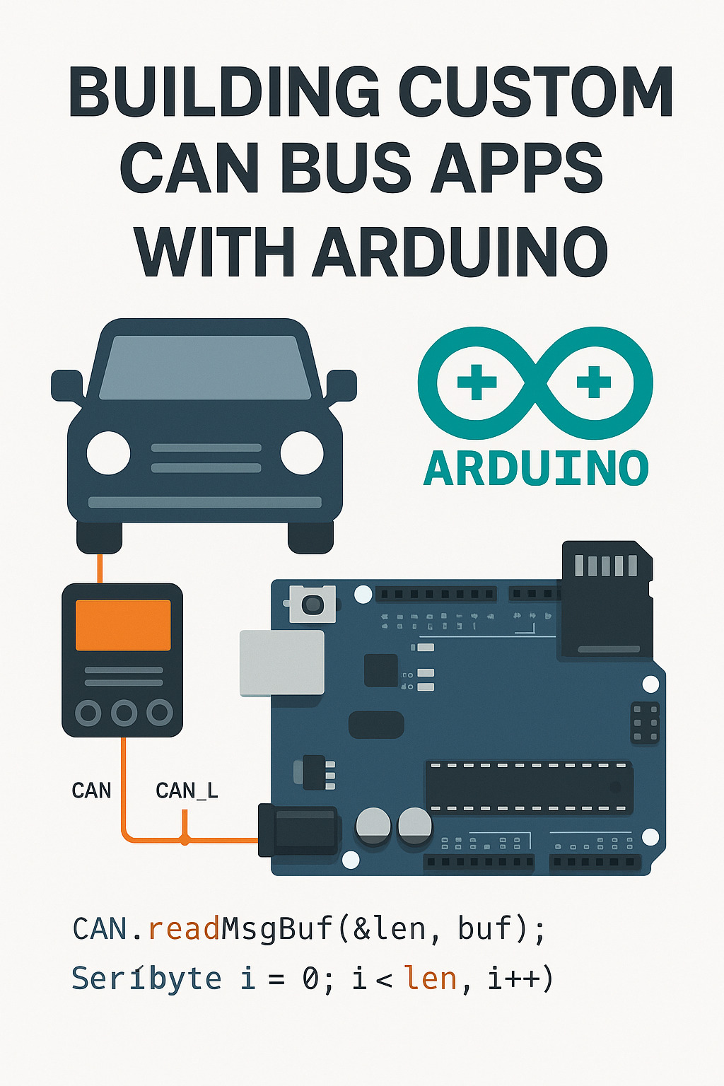
Building Custom CAN Bus Applications with Arduino: A Developer’s Guide
Description: Learn how to interface with your vehicle’s CAN Bus system using Arduino. This guide covers hardware setup, coding, and real-world use cases for building custom vehicle apps and diagnostics tools.
Introduction
Today’s vehicles are filled with electronic control units (ECUs) that communicate over the Controller Area Network (CAN Bus). By tapping into this system, developers and enthusiasts can read vehicle data, trigger actions, and build custom dashboards or automation tools.
In this post, we’ll walk through how to use Arduino to develop your own CAN Bus applications—whether you’re building diagnostic tools, custom infotainment interfaces, or performance monitors.
What You Need
Hardware Components:
- Arduino Uno, Mega, Nano, or compatible board
- MCP2515 CAN Bus module with TJA1050 transceiver (SPI)
- Jumper wires or breadboard
- OBD-II to DB9 or bare wire harness (depending on your access method)
- 12V to 5V voltage regulator (for vehicle power)
Software and Libraries:
- Arduino IDE
mcp_canlibrary (by Seeed Studio or Cory Fowler)- Optional: OLED display, SD card module, Bluetooth module, or Wi-Fi shield
Wiring Overview
The MCP2515 module communicates via SPI. Here’s a standard wiring map:
| MCP2515 Module | Arduino Uno |
|---|---|
| VCC | 5V |
| GND | GND |
| CS | D10 |
| SO | D12 |
| SI | D11 |
| SCK | D13 |
| INT | D2 |
Connect CAN_H and CAN_L lines from the vehicle’s OBD-II port (pins 6 and 14) or directly from a CAN tap if available.
Sample Code: Reading CAN Messages
#include <mcp_can.h>
#include <SPI.h>

const int SPI_CS_PIN = 10;
MCP_CAN CAN(SPI_CS_PIN);

void setup() {
  Serial.begin(115200);
  while (CAN_OK != CAN.begin(CAN_500KBPS)) {
    Serial.println("CAN BUS init Failed");
    delay(100);
  }
  Serial.println("CAN BUS init OK");
}

void loop() {
  unsigned char len = 0;
  unsigned char buf[8];
  if (CAN_MSGAVAIL == CAN.checkReceive()) {
    CAN.readMsgBuf(&len, buf);
    unsigned long canId = CAN.getCanId();
    Serial.print("ID: ");
    Serial.print(canId, HEX);
    Serial.print(" Data: ");
    for (int i = 0; i < len; i++) {
      Serial.print(buf[i], HEX);
      Serial.print(" ");
    }
    Serial.println();
  }
}
This script initializes the CAN interface and prints out raw CAN messages. From here, you can parse specific IDs for things like RPM, throttle position, or speed.
Real-World Applications
- Custom Gauges: Display real-time vehicle data on an OLED or TFT screen.
- Data Logging: Store CAN traffic to an SD card for later analysis.
- Remote Monitoring: Send CAN data via Bluetooth or Wi-Fi to a mobile app.
- Command Injection: Send commands to vehicle systems (where legal and safe).
- Security Research: Monitor for spoofed or malicious CAN frames.
Considerations and Safety
- Always verify CAN frame formats before sending data.
- Isolate the CAN circuitry with opto-isolators or buffers when possible.
- Never interfere with safety-critical systems like brakes or airbags.
- Use a fused, regulated power supply if drawing power from the vehicle.
Conclusion
Developing custom CAN Bus applications with Arduino is both accessible and powerful. With the right hardware, a few open-source libraries, and some creativity, you can build everything from diagnostic tools to full-featured performance systems.
In a future post, we’ll dive deeper into decoding specific CAN messages and building a live dashboard with custom displays.

